Advanced Paralleling Gen-Set Controllers
c
DSEG8900
7" Colour Parallel Genset Controller
The DSEG8900 is a 7” colour parallel genset controller designed for complex paralleling applications. The DSEG8900 can be configured to provide single-set and multi-set paralleling on a single site and provides a wide range of high-end features for multiple application environments.
OVERALL SIZE
305 mm x 161 mm x 45.2 mm / 12 ” x 6.34 ” x 1.77 ”
PANEL CUTOUT SIZE
282 mm x 136 mm / 11.1 ” x 5.35 ”
MAXIMUM PANEL THICKNESS
8.0 mm / 0.31 ”
PRODUCT VARIANTS
G8900-01
305 mm x 161 mm x 45.2 mm / 12 ” x 6.34 ” x 1.77 ”
PANEL CUTOUT SIZE
282 mm x 136 mm / 11.1 ” x 5.35 ”
MAXIMUM PANEL THICKNESS
8.0 mm / 0.31 ”
PRODUCT VARIANTS
G8900-01
Request a Quote
Product Highlights
Key Features
2 module applications in one product (single-set and multi-set)
Flexible bus segments
Slip sync and sync (phase) lock synchronising control
Advanced multi-set communication (AMSC) link with optional redundancy
Shared virtual inputs, outputs and data via AMSC
Advanced PLC functionality including multi-purpose PIDs
Flexible inputs and outputs
DSENet® Expansion Support
PC configuration using DSE Configuration Suite
Multiple language support
Enhanced 7" high resolution colour display with on screen application diagrams
Integrated gasket (IP65 protection)
2 integrated RS485 ports providing Modbus RTU support
Integrated Ethernet port providing Modbus TCP and SNMP v2C support
Data logging of up to 20 parameters
Manual front panel and automatic control modes
Specification
DC Supply
CONTINUOUS VOLTAGE RATING8 V to 35 V DC continuous
CRANKING DROPOUTS
Able to survive 0 V for 100 mS, providing supply was at least 10 V before dropout and supply recovers to 5 V. This is achieved without the need for internal batteries. LEDs and backlight will not be maintained during cranking.
MAXIMUM OPERATING CURRENT
985 mA at 12 V, 500 mA at 24 V
MAXIMUM STANBY CURRENT
725 mA at 12 V, 370 mA at 24 V
Voltage Measurement
NUMBER2
MEASUREMENT INPUTS
3 Phase + Neutral
Single- Set Controller: Generator and Mains (Utility)
Multi-Set Controller: Generator and Bus
VOLTAGE RANGE
15 V to 415 V (Ph to N)
25 V - 720 V (Ph to Ph)
FREQUENCY RANGE
3.5 Hz to 75 Hz
Current Transformer Measurement
NUMBER5
MEASUREMENT INPUTS
3 Phase with Earth Fault, and Single Phase
Single-Set Controller: 3 Phase Generator Current with Earth Fault Current + Single
Phase Mains (Utility) Current
Multi-Set Controller: 3 Phase Generator Current with Earth Fault Current
CURRENT Range
0 to 1 A
0 to 5 A
Inputs
ANALOGUENumber: 7
Type: Negative Switching Digital Input, Resistive Analogue Input, Current Analogue Input or Voltage Analogue Input
DIGITAL
Number: 9
Type: Negative Switching Digital Input
EMERGENCY STOP INPUT
Number: 1
Type: Positive Switching Digital Input
MAGNETIC PICK-UP INPUT
Voltage Input Range: 0.5 VPeak to 70 VPeak
Frequency Input Range: 1 Hz to 10 kHz
Outputs
ANALOGUENumber: 2
Type: Current Analogue Output or Voltage Analogue Output
DIGITAL
Number: 12
Type:
1 Normally Open Volt-Free Contacts
1 Normally Closed Volt-Free Contacts
10 Positive Switching DC Output
Communications
USB A1 Data Storage Port
USB B
1 Programming Port
DSENet®
1 Expansion Port
RS485
2 Fully Isolated RS485 Ports
ETHERNET
1 10/100 Ethernet Port
CAN
4 Fully Isolated CAN Ports
Single-Set Controller:
CAN 1 – Engine ECU/ECM
CAN 2 – Not Used
CAN 3 – Not Used
CAN 4 - Not Used
Multi-Set Controller:
CAN 1 – Engine ECU/ECM
CAN 2 – AMSC
CAN 3 or CAN 4 – Redundant AMSC
Environmental Testing Standards
Environmental Testing Standards
Electro-Magnetic Compatibility
BS EN 61000-6-2
EMC Generic Immunity Standard for the Industrial Environment
EMC Generic Immunity Standard for the Industrial Environment
BS EN 61000-6-4
EMC Generic Emission Standard for the Industrial Environment
EMC Generic Emission Standard for the Industrial Environment
Electrical Safety
BS EN 61010
Safety of Information Technology Equipment, including Electrical Business Equipment
Safety of Information Technology Equipment, including Electrical Business Equipment
Temperature
BS EN 60068-2-1
Ab/Ae Cold Test -30 ºC
Ab/Ae Cold Test -30 ºC
BS EN 60068-2-2
Bb/Be Dry Heat +70 ºC
Bb/Be Dry Heat +70 ºC
Vibration
BS EN 60068-2-6
Ten sweeps in each of three major axes
Ten sweeps in each of three major axes
5 Hz to 8 Hz at +/-7.5 mm,
8 Hz to 500 Hz at 2 gn
Humidity
BS EN 60068-2-30
Db Damp Heat Cyclic 20/55 ºC at 95% RH 48 Hours
Db Damp Heat Cyclic 20/55 ºC at 95% RH 48 Hours
BS EN 60068-2-78
Cab Damp Heat Static 40 ºC at 93% RH 48 Hours
Cab Damp Heat Static 40 ºC at 93% RH 48 Hours
Shock
BS EN 60068-2-27
Three shocks in each of three major axes
Three shocks in each of three major axes
15 gn in 11 mS
Degrees of Protection Provided by Enclosures
BS EN 60529 IP65 - Front of module when installed into the control panel (Integrated Gasket)
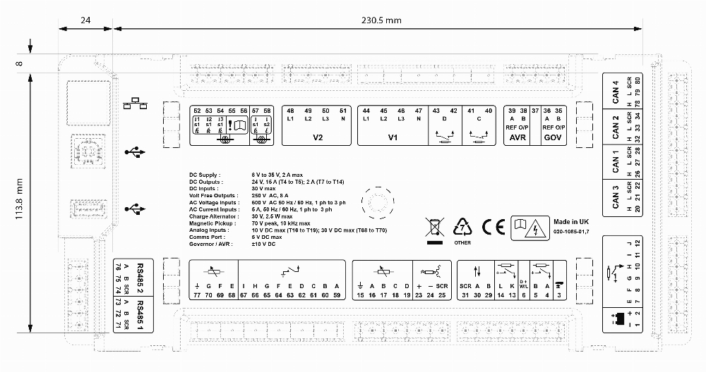
Connection Diagram