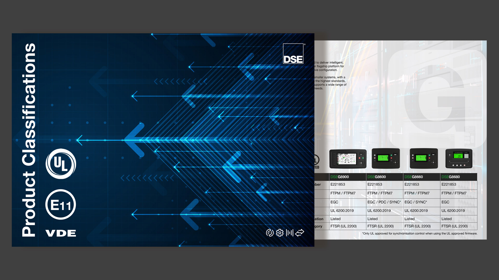
Advanced Paralleling Gen-Set Controllers
c
DSEG8680
Bus-Tie Controller
The DSEG8680 Bus-Tie controller is designed to work with the DSEG8660 and DSEG8600 (configured for use as a multi-set controller, mains (utility) controller or group controller) to provide control solutions for complicated system design. The DSEG8680 is configurable for use as a bus-tie controller or load switch controller. This enables the controller to use the AMSC (Advanced Multi-Set Communications) link to synchronise two bus segments together within a DSEG8xxx system and allow them to operate in parallel.
OVERALL SIZE
250 mm x 189 mm x 50.5 mm / 9.85 ” x 7.43 ” x 1.99 ”
PANEL CUTOUT SIZE
220 mm x 160 mm / 8.66 " x 6.30 "
MAXIMUM PANEL THICKNESS
8.0 mm / 0.31 ”
PRODUCT VARIANTS
G8680-01
250 mm x 189 mm x 50.5 mm / 9.85 ” x 7.43 ” x 1.99 ”
PANEL CUTOUT SIZE
220 mm x 160 mm / 8.66 " x 6.30 "
MAXIMUM PANEL THICKNESS
8.0 mm / 0.31 ”
PRODUCT VARIANTS
G8680-01
Request a Quote
Product Highlights
Key Features
2 module applications in one product (bus-tie and load switch)
Flexible bus segments
Advanced multi-set communication (AMSC) link with optional redundancy
Shared virtual inputs, outputs and data via AMSC
Advanced PLC functionality including multi-purpose PIDs
Flexible inputs and outputs
DSENet® Expansion Support
PC configuration using DSE Configuration Suite
Multiple language support
4-line back-lit LCD
IP65 with supplied sealing gasket
RS485 port providing Modbus RTU Support
Integrated Ethernet port providing Modbus TCP and SNMP v2C support
Data logging of up to 20 parameters
Manual front panel and automatic control modes
Specification
DC Supply
CONTINUOUS VOLTAGE RATING8 V to 35 V DC continuous
CRANKING DROPOUTS
Able to survive 0 V for 100 ms, providing supply was at least 10 V before dropout and supply recovers to 5 V. This is achieved without the need for internal batteries. Backlight will not be maintained during cranking.
MAXIMUM OPERATING CURRENT
530 mA at 12 V, 280 mA at 24 V
MAXIMUM STANDBY CURRENT
320 mA at 12 V, 120 mA at 24 V
Voltage Measurement
NUMBER2
MEASUREMENT INPUTS
3 Phase + Neutral
VOLTAGE RANGE
15 V to 415 V Phase to Neutral
25 V to 719 V Phase to Phase
FREQUENCY RANGE
3.5 Hz to 75 Hz
Current Transformer Measurement
NUMBER4
MEASUREMENT INPUTS
3 Phase with Email Fault
CURRENT RANGE
0 A to 1 A
0 A to 5 A
Digital Inputs / Output
INPUTS
Number: 12
Type: Negative Switching Digital Input
Closed Voltage Threshold: Less than 2.1 V
Open Voltage Threshold: Greater than 6.6 V
OUTPUTS
Number: 10
Type: 1 Normally Open Volt-Free Contact, 1 Normally Closed Volt-Free Contact, 8 Positive Switching DC Output
Volt-Free Contact Output Rating: 5 A DC resistive at 30 V DC, 8 A AC resistive at 250 V AC
Positive DC Output Rating: 2 A DC at module supply voltage
Environmental Testing Standards
Electro-Magnetic Compatibility
BS EN 61000-6-2 - EMC Generic Immunity Standard for the Industrial Environment
BS EN 61000-6-4 - EMC Generic Emission Standard for the Industrial Environment
Electrical Safety
BS EN 61010 - Safety of Information Technology Equipment, including Electrical Business Equipment
Temperature
BS EN 60068-2-1 - Ab/Ae Cold Test -30°C
BS EN 60068-2-2 - Bb/Be Dry Heat +70°C
Vibration
BS EN 60068-2-6 - Ten sweeps in each of three major axes
5Hz to 8 Hz at +/-7.5mm
8Hz to 500 Hz at 2gn
Humidity
BS EN 60068-2-30 - Db Damp Heat Cyclic 20/55°C at 95% RH 48 Hours
BS EN 60068-2-78 - Cab Damp Heat Static 40°C at 93% RH 48 Hours
Shock
BS EN 60068-2-27 - Three shocks in each of three major axes
15 gn in 11 ms
Degrees of Protection Provided by Enclosures
BS EN 60529 - IP65 - Front of module when installed into the control panel (Integrated Gasket)
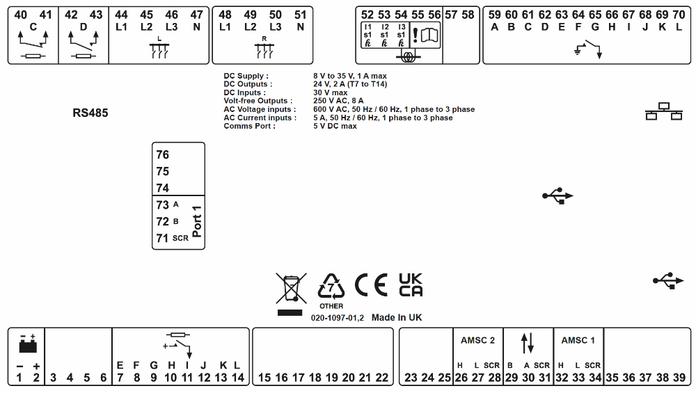
Connection Diagram