Advanced Paralleling Gen-Set Controllers
c
DSEG8600
Parallel Genset Controller with Integral Heater
User Configurable as: Single-Set Controller / Multi-Set Controller/ Mains (Utility) Controller / Group Controller
The G8600 is a parallel genset controller with integral heater designed for complex paralleling applications. The G8600 can be configured to provide paralleling for up to 4,032 generators on a single site and provides a wide range of high-end features for multiple application environments. The module is configurable for use as a single-set controller, multi-set controller, mains (utility) controller or group controller.
The G8600 is a parallel genset controller with integral heater designed for complex paralleling applications. The G8600 can be configured to provide paralleling for up to 4,032 generators on a single site and provides a wide range of high-end features for multiple application environments. The module is configurable for use as a single-set controller, multi-set controller, mains (utility) controller or group controller.
Overall (W x H x D)
248 mm x 182.6 mm x 45.2 mm / 9.77” x 7.19” x 1.78”
Panel Cut-Out (W x H)
220 mm x 160 mm / 8.66” x 6.3”
Maximum Panel Thickness
8 mm / 0.31”
248 mm x 182.6 mm x 45.2 mm / 9.77” x 7.19” x 1.78”
Panel Cut-Out (W x H)
220 mm x 160 mm / 8.66” x 6.3”
Maximum Panel Thickness
8 mm / 0.31”
Request a Quote
Product Highlights
Key Features
Multiple bus sectioning
Group controller functionality
Spinning reserve
Load demand schemes
Advanced MSC link (AMSC)
Advanced PLC functionality
Multi-purpose PIDs
Phase locking
Virtual inputs
On-screen mimic (SLDs)
Multiple application support
Multi-level pin protected front panel editor
Integral LCD display heater
Enhanced high-resolution 240 x 128 pixel display
Single or multiple generator control
Latest ECU / ECM support
Load sharing & VAr sharing
Virtual shared inputs / outputs and data via AMSC
Touch screen panel PC support (DSE SCADA)
Zero Sequence voltage protection
Integral gasket (IP65 protection)
- Additional Features
- Built-in governor & AVR control
- DSE digital AVR support
- Base load (kW export) control
- Positive & negative kVAr export control
- Dead bus synchronising
- Mains (utility) decoupling protection
- Multiple language support
- 3-phase generator sensing & protection
- 3-phase mains (utility) sensing
- 3-phase bus sensing
- Mains (utility) failure detection
- Generator current, protection & power monitoring
- Configurable timers
- Integrated SNMP
- Data logging
- PC configuration
- DSENet® Expansion Support
- Flexible I/O (inputs/outputs)
- Automatic and front panel breaker control
- Power-save mode
Specification
DC Supply
Continuous Voltage Rating8 V to 35 V DC continuous
Cranking Dropouts Able to survive 0 V for 100 mS, providing supply was at least 10 V before dropout and supply recovers to 5 V. This is achieved without the need for internal batteries. LEDs and backlight will not be maintained during cranking.
Maximum Operating Current
700 mA at 12 V, 350 mA at 24 V
Maximum Standby Current
350 mA at 12 V, 190 mA at 24 V
Charge Fail Excitation Range
0 V to 35 V
Real Time Clock Battery
Not replaceable
Voltage Measurement
Measurement Inputs3 ph + N
Measurement Range
15 V to 415 V (L-N) / 25 V - 719 V (Ph-Ph)
Accuracy
1% full scale
Frequency Range
3.5 Hz to 75 Hz
Input Impedance
450 K L-L
Current Measurement
Measurement Inputs3-phase & neutral
Measurement Range
0-1 A, 0-5 A
Max Allowed Continuous Current
5 A
Accuracy
1% full scale
Input Impedance
0.02 R
Inputs
Analogue4 sender inputs configurable 1 x 0-3 K, 3 x 0-5 K
Digital (Flexible)
3 configurable, active low / active high, 0-3 K resistance, 0-10 V, 0-32 V, 0-20 mA
Digital
9 active low digital outputs
Type
Standard senders with floating common, digital flex use system ground with separate return terminal
Resolution
1 R, 0.1 V, 0.1 mA
Accuracy
1% full range
Outputs
AnalogueGovernor / AVR configurable ±10 V, ±20 mA
Digital
Fuel / crank protected FET output 15 A
Auxiliary
8 protected FET @ 2 A
Switching To
Plant supply
Volt-Free Contact
2 volt-free contacts (C & D) 8 A at 250 V AC
AVR Governor Control
Minimum Load ImpedanceVoltage mode minimum = 500 R, Current mode max = 500 R
Gain Voltage
0-10 V, 0-20 mA configurable
Offset Voltage
0-10 V, 0-20 mA configurable
Magnetic Pick-Up
Voltage Input Range0.5 V to 70 V RMS
Frequency Input Range
1 Hz to 10 KHz
Frequency Measurement Tolerance
Better than 0.1%
Communications
RS485Fully isolated x 2
Ethernet
10/100 Ethernet Port
USB A
1 x storage device
USB B
1 x non isolated host / programming
CAN
Fully isolated x 3
Temperature
Operating Temperature-30° C to +70 ° C / -22° F to +158 ° F
Storage Temperature
-40° C to +85 ° C / -40° F to +185 ° F
Dimensions
Overall (W x H x D)248 mm x 182.6 mm x 45.2 mm / 9.77” x 7.19” x 1.78”
Panel Cut-Out (W x H)
220 mm x 160 mm / 8.66” x 6.3”
Maximum Panel Thickness
8 mm / 0.31”
Environmental Testing Standards
Electro-Magnetic Compatibility
BS EN 61000-6-2 - EMC Generic Immunity Standard for the Industrial Environment
BS EN 61000-6-4 - EMC Generic Emission Standard for the Industrial Environment
Electrical Safety
BS EN 61010 - Safety of Information Technology Equipment, including Electrical Business Equipment
Temperature
BS EN 60068-2-1 - Ab/Ae Cold Test -30°C
BS EN 60068-2-2 - Bb/Be Dry Heat +70°C
Vibration
BS EN 60068-2-6 - Ten sweeps in each of three major axes
5Hz to 8 Hz at +/-7.5mm
8Hz to 500 Hz at 2gn
Humidity
BS EN 60068-2-30 - Db Damp Heat Cyclic 20/55°C at 95% RH 48 Hours
BS EN 60068-2-78 - Cab Damp Heat Static 40°C at 93% RH 48 Hours
Shock
BS EN 60068-2-27 - Three shocks in each of three major axes
15 gn in 11 ms
Degrees of Protection Provided by Enclosures
BS EN 60529 - IP65 - Front of module when installed into the control panel (Integrated Gasket)
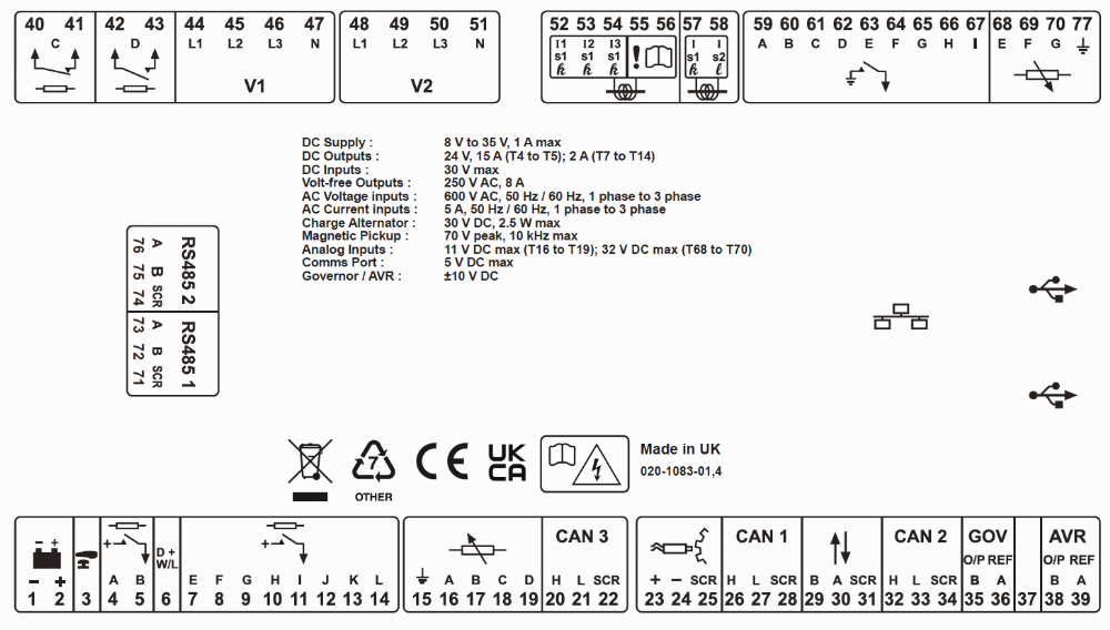
Connection Diagram