Auto Mains (Utility) Failure Control Modules
c
DSE7320 MKII
Auto Mains (Utility) Failure Control Module
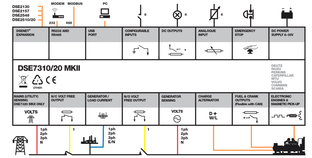
The DSE7320 MKII is an auto mains (utility) failure control module suitable for a wide variety of single, diesel or gas, gen-set applications. Monitoring an extensive number of engine parameters, the modules will display warnings, shutdown and engine status information on the back-lit LCD screen, illuminated LEDs and remote PC.
The DSE7320 MKII also monitor the mains (utility) supply. The module include USB, RS232 and RS485 ports as well as dedicated DSENet® terminals for system expansion. The module is compatible with electronic (CAN) and non-electronic (magnetic pick-up/alternator sensing) engines and offer an extensive number of flexible inputs, outputs and extensive engine protections so the system can be easily adapted to meet the most demanding industry requirements. The extensive list of features includes enhanced event and performance monitoring, remote communications & PLC functionality.
The module can be easily configured using the DSE Configuration Suite PC software. Selected front panel editing is also available.
OVERALL SIZE
245 mm x 184 mm x 51 mm (9.6" x 7.2" x 2.0")
PANEL CUTOUT SIZE
220 mm x 160 mm (8.7" x 6.3")
MAXIMUM PANEL THICKNESS
8.0 mm (0.3")
Request a Quote

Product Highlights
Key Features
Advanced PLC functionality including multi-purpose PIDs
Flexible inputs and outputs
DSENet® Expansion Support
PC configuration using DSE Configuration Suite
Multiple language support
Enhanced 4-line text display
Integrated RS232 and RS485 ports providing Modbus RTU support
Data logging of up to 10 parameters
Multi-level pin protected front panel editor
Manual front panel and automatic control modes
Latest ECU / ECM support for a wide range of engine manufacturers
Multiple selectable configurations
Customisable module power-up & screen saver screens
IP65 rating (with supplied gasket) offers increased resistance to water ingress
3 phase generator and mains (utility) sensing with protection
Manual starting / control by fascia button and automatic starting / control by inputs and other functions
Automatic start and stopping of generator and transfer of load based on mains (utility) availability
Specification
DC SUPPLY
CONTINUOUS VOLTAGE RATING8 V to 35 V Continuous
CRANKING DROPOUTS
Able to survive 0 V for 100 mS, providing supply was at least 10 V before dropout and supply recovers to 5 V. This is achieved without the need for internal batteries. Backlight will not be maintained during cranking.
MAXIMUM OPERATING CURRENT
340 mA at 12 V, 160 mA at 24 V
MAXIMUM STANDBY CURRENT
160 mA at 12 V, 80 mA at 24 V
CHARGE FAIL/EXCITATION RANGE
0 V to 35 V
GENERATOR & MAINS (UTILITY)
VOLTAGE RANGE15 V to 415 V AC (Ph to N)
25 V to 720 V AC (Ph to Ph)
FREQUENCY RANGE
3.5 Hz to 75 Hz
MAGNETIC PICK UP
VOLTAGE RANGE+/- 0.5 V to 70 V
FREQUENCY INPUT RANGE
5 Hz to 10 kHz
Environmental Testing Standards
Electro-Magnetic Compatibility
BS EN 61000-6-2 EMC Generic Immunity Standard for the Industrial Environment
BS EN 61000-6-4 EMC Generic Emission Standard for the Industrial Environment
Electrical Safety
BS EN 61010 Safety of Information Technology Equipment, including Electrical Business Equipment
Temperature
BS EN 60068-2-1 Ab/Ae Cold Test -30 ºC
BS EN 60068-2-2 Bb/Be Dry Heat +70 ºC
Vibration
BS EN 60068-2-6 Ten sweeps in each of three major axes
5 Hz to 8 Hz at ±7.5 mm,
8 Hz to 500 Hz at 2 Gn
Humidity
BS EN 60068-2-30 Db Damp Heat Cyclic 20/55 ºC at 95% Relative Humidity 48 Hours
BS EN 60068-2-78 Cab Damp Heat Static 40 ºC at 93% Relative Humidity 48 Hours
Shock
BS EN 60068-2-27 Three shocks in each of three major axes
15 Gn in 11 ms
Degrees of Protection Provided by Enclosures
BS EN 60529 IP65 - IP65 - From the front of the module when the gasket is installed into a control panel.
Connection Diagram
Product Variants
7320-03 - 7320 MKII Auto Mains (Utility) Failure Control Module