Manual & Auto Start Control Modules
DSE7410 MKII
Auto Start Control Module
250.0 mm x 189.0 mm x 50.5 mm / 9.85 ” x 7.43 ” x 1.99 ”
PANEL CUTOUT SIZE
220.0 mm x 160.0 mm / 8.66 " x 6.30 "
MAXIMUM PANEL THICKNESS
8.0 mm / 0.3 ”
PRODUCT VARIANTS
7410-03
Request a Quote

Product Highlights
Key Features
Specification
DC Supply
CONTINUOUS VOLTAGE RATING8 V to 35 V DC Continuous
CRANKING DROPOUTS
Able to survive 0 V for 100 ms, providing supply was at least 10 V before dropout and supply recovers to 5 V. This is achieved without the need for internal batteries. Backlight will not be maintained during cranking
MAXIMUM OPERATING CURRENT
340 mA at 12 V, 160 mA at 24 V
MAXIMUM STANDBY CURRENT
160 mA at 12 V, 80 mA at 24 V
CHARGE ALTERNATOR EXCITATION / FAIL RANGE
0 V to 35 V
Inputs
ANALOGUE INPUTS
Number: 6
Type: Negative Switching Digital Input (6), Resistive Analogue Input (6), Current Analogue Input (4) and Voltage Analogue Input (4)
DIGITAL INPUTS
Number: 8
Type: Negative Switching Digital Input
EMERGENCY STOP INPUT
Number: 1
Type: Positive Switching Digital Input
MAGNETIC PICK-UP INPUT
Voltage Input Range: 0.5 VPeak to 70 VPeak
Frequency Input Range: 5 Hz to 10 kHz
Outputs
DIGITAL OUTPUTSNumber: 10
Type:
Environmental Testing Standards
ELECTRO-MAGNETIC COMPATIBILITY
BS EN 61000-6-2
EMC Generic Immunity Standard for the Industrial Environment.
BS EN 61000-6-4
EMC Generic Emission Standard for the Industrial Environment.
ELECTRICAL SAFETY
BS EN 60950
Safety of Information Technology Equipment, including Electrical Business Equipment.
TEMPERATURE
BS EN 60068-2-1
Ab/Ae Cold Test -30°C.
BS EN 60068-2-2
Bb/Be Dry Heat +70°C.
VIBRATION
BS EN 60068-2-6
Ten sweeps in each of three major axes.
5 Hz to 8 Hz @ +/-7.5 mm, 8 Hz to 500 Hz @ 2 gn.
HUMIDITY
BS EN 60068-2-30
Db Damp Heat Cyclic 20/55° C @ 95% RH 48 Hours.
BS EN 60068-2-78
Cab Damp Heat Static 40° C @ 93% RH 48 Hours.
SHOCK
BS EN 60068-2-27
Three shocks in each of three major axes 15 gn in 11 ms.
BS EN 60529
IP65 - Front of module when installed into the control panel with the supplied sealing gasket.
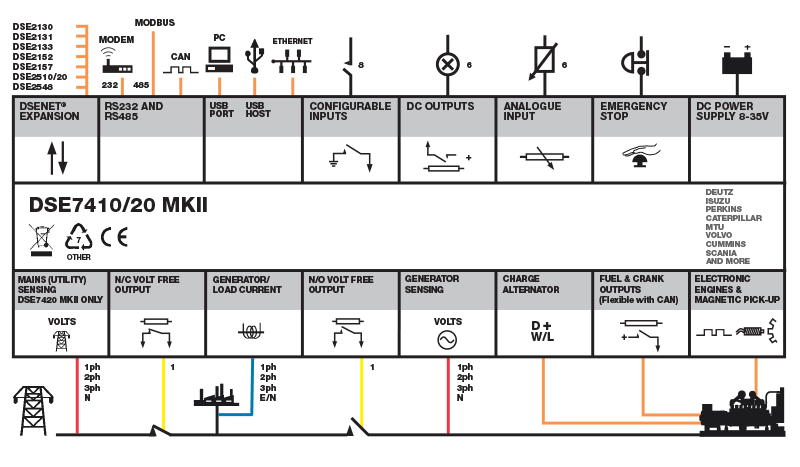
Connection Diagram