Auto Mains (Utility) Failure Control Modules
DSE7420 MKII
Auto Mains (Utility) Failure Control Module
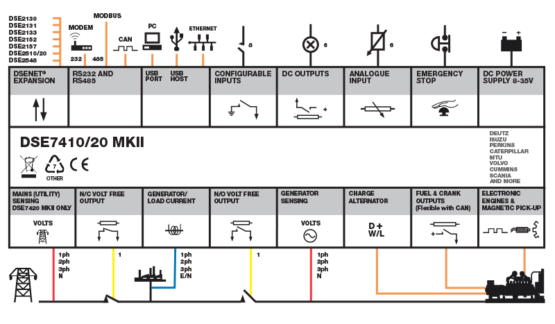
The module is compatible with electronic (CAN) and non-electronic (magnetic pick-up/alternator sensing) engines and offer an extensive number of flexible inputs, outputs and engine protections so the system can be easily adapted to meet the most demanding industry requirements. The comprehensive list of features includes enhanced event and performance monitoring, remote communications & PLC functionality. Dual mutual standby is now available on both the DSE7420 MKII using RS232 or RS485 communications.
250.0 mm x 189.0 mm x 50.5 mm / 9.85 ” x 7.43 ” x 1.99 ”
PANEL CUTOUT SIZE
220.0 mm x 160.0 mm / 8.66 " x 6.30 "
MAXIMUM PANEL THICKNESS
8.0 mm / 0.3 ”
PRODUCT VARIANTS
7420-03
Request a Quote
Product Highlights
Key Features
Specification
DC Supply
CONTINUOUS VOLTAGE RATING8 V to 35 V DC Continuous
CRANKING DROPOUTS
Able to survive 0 V for 100 ms, providing supply was at least 10 V before dropout and supply recovers to 5 V. This is achieved without the need for internal batteries. Backlight will not be maintained during cranking
MAXIMUM OPERATING CURRENT
340 mA at 12 V, 160 mA at 24 V
MAXIMUM STANDBY CURRENT
160 mA at 12 V, 80 mA at 24 V
CHARGE ALTERNATOR EXCITATION / FAIL RANGE
0 V to 35 V
Inputs
ANALOGUE INPUTS
Number: 6
Type: Negative Switching Digital Input (6), Resistive Analogue Input (6), Current Analogue Input (4) and Voltage Analogue Input (4)
DIGITAL INPUTS
Number: 8
Type: Negative Switching Digital Input
EMERGENCY STOP INPUT
Number: 1
Type: Positive Switching Digital Input
MAGNETIC PICK-UP INPUT
Voltage Input Range: 0.5 VPeak to 70 VPeak
Frequency Input Range: 5 Hz to 10 kHz
Outputs
DIGITAL OUTPUTSNumber: 10
Type:
Environmental Testing Standards
ELECTRO-MAGNETIC COMPATIBILITY
BS EN 61000-6-2
EMC Generic Immunity Standard for the Industrial Environment.
BS EN 61000-6-4
EMC Generic Emission Standard for the Industrial Environment.
ELECTRICAL SAFETY
BS EN 60950
Safety of Information Technology Equipment, including Electrical Business Equipment.
TEMPERATURE
BS EN 60068-2-1
Ab/Ae Cold Test -30°C.
BS EN 60068-2-2
Bb/Be Dry Heat +70°C.
VIBRATION
BS EN 60068-2-6
Ten sweeps in each of three major axes.
5 Hz to 8 Hz @ +/-7.5 mm, 8 Hz to 500 Hz @ 2 gn.
HUMIDITY
BS EN 60068-2-30
Db Damp Heat Cyclic 20/55° C @ 95% RH 48 Hours.
BS EN 60068-2-78
Cab Damp Heat Static 40° C @ 93% RH 48 Hours.
SHOCK
BS EN 60068-2-27
Three shocks in each of three major axes 15 gn in 11 ms.
BS EN 60529
IP65 - Front of module when installed into the control panel with the supplied sealing gasket.
Connection Diagram