Lighting Tower Control Modules

DSEL401 MKII

Intelligent Lighting Tower Control Module

The DSEL401 MKII is an intelligent control module designed specifically for mobile lighting tower applications. The control module provides class leading flexible features that are fully configurable to suit multiple complex lighting sequences. 

To view UL Certification click here

OVERALL SIZE
140 mm x 113 mm x 43 mm (5.5” x 4.4” x 1.7”) 
PANEL CUTOUT SIZE
118 mm x 92 mm (4.6” x 3.6”) 
MAXIMUM PANEL THICKNESS
8.0mm (0.3”)
WEIGHT
0.28kg
PRODUCT VARIANTS
L401-01 - L401 MKII Intelligent Lighting Tower Control Module (Rtc)

Request a Quote

e -
Please select a product
Please enter a quantity
e +

add another product

Please enter your title
Please enter your first name
Please enter your surname
Please enter your company name
Please select your country
Please enter a delivery Country/State
Please enter your email
Please enter your mobile number
Webform URL: Website Option: Webform: Named Distributor: Distributor's Email: Named Reseller: Reseller's Email:


l

Product Highlights

Key Features & Benefits

Key Features

Key Benefits

Large back-lit icon LCD display.
Displays information to the operator in a clear and concise format.
Configurable outputs (8 DC, 3 analogue/digital).
Provides multiple installation options.
Configurable staged light control outputs.
Prevents engine from stalling.
Heated display option.
Ensures the display continues to operate in extreme cold weather conditions.
Power monitoring (kW h, kV Ar, kV Ah, kV Ar h).
Provides clear accurate power measurement information.
Automatic & manual light control.
Allows lights to be controlled manually or turn on automatically when daylight reduces (sensor required).
Individual lighting control.
Avoids permanent light failure during restart.
Light failure detection.
Informs the operator of the exact bulbs that need replacing.
Comprehensive fuel monitoring.
When fuel reaches a certain level the lights can be dimmed to increase available running hours.
Event scheduler (16).
Can be programmed to operate up to 4 staged load outputs.
Engine speed protection, engine hours counter, engine pre-heat, engine run-time scheduler, engine idle control for start/stop.
Ensures the engine is fully monitored for improved operating performance.
Start on low battery.
Ensures the battery does not fully discharge. Engine runs until battery is charged.
Configurable event log (50).
Provides access to historical alarms and operational status.
DSE Configuration Suite PC Software.
Provides complete user-friendly configuration and easy-to-use high-level system control & monitoring.
Sunset/sunrise algorithm within scheduler.
Enables the controller to be configured to run automatically between the hours of sunset and sunrise.
Multi-level PIN support.
Multiple access level PIN numbers can be added for different operators.
Block heater digital output.
Allows a block heater to be configured to run between 0 seconds and 60 minutes prior to engine start up.
Fuel pull-in coil output.
Pulls the fuel solenoid in place whilst the engine starts.
Disable auto mast control.
Provides a dedicated input to keep the mast in place.
Generator only manual mode.
The lighting tower can be run as a generator only in manual mode.
Disable warnings.
Warnings can be programmed not to show on the modules display.
Generator within standards.
An output has been provided for when the voltage or frequency is between the low voltage and high voltage pre-alarms. If it goes outside the range the output goes off.
Holding supports open.
An icon on the front panel display indicates if the lighting tower holding supports are in or out.
Raise and lower mast.
A single input source is available when active to raise the mast and when inactive lower the mast.
  • Additional Features
  • Power save mode.
  • 3-phase generator sensing.
  • Generator/load current monitoring & protection.
  • 600 V ph-ph nominal system compatibility.
  •  
  • Fuel & crank outputs.
  • CAN & alternator speed sensing.
  • Engine maintenance alarms (3).
  •  
  • Alternative configuration (1).

Specification

DC SUPPLY

CONTINUOUS VOLTAGE RATING
8 V to 35 V Continuous

CRANKING DROPOUTS
Able to survive 0 V for 50 mS, providing supply was at least 10 V before dropout and supply recovers to 5 V. This is achieved without the need for internal batteries. LEDs and backlight will not be maintained during cranking.

MAXIMUM OPERATING CURRENT
85 mA at 12 V, 96 mA at 24 V

MAXIMUM STANDBY CURRENT
51 mA at 12 V, 47 mA at 24 V

MAXIMUM SLEEP CURRENT
35 mA at 12 V, 32 mA at 24 V

MAXIMUM DEEP SLEEP CURRENT
<10 uA at 12 V, <10 uA at 24 V

OUTPUTS

OUTPUT A (FUEL)
10 A short term, 5 A continuous,
at supply voltage

OUTPUT B (START)
10 A short term, 5 A continuous,
at supply voltage

AUXILIARY OUTPUTS C to J
2 A DC at supply voltage ­­

GENERATOR

VOLTAGE RANGE
15 V to 415 V AC (Ph to N)
26 V to 719 V AC (Ph to Ph)

FREQUENCY RANGE
3.5 Hz to 75 Hz

Environmental Testing Standards

ELECTRO-MAGNETIC  COMPATIBILITY
BS EN 61000-6-2
EMC Generic Immunity Standard for the Industrial Environment.
BS EN 61000-6-4
EMC Generic Emission Standard for the Industrial Environment.

ELECTRICAL SAFETY
BS EN 60950
Safety of Information Technology Equipment, including Electrical Business Equipment.

TEMPERATURE
BS EN 60068-2-1
Ab/Ae Cold Test -30°C.
BS EN 60068-2-2
Bb/Be Dry Heat +70°C.

VIBRATION
BS EN 60068-2-6
Ten sweeps in each of three major axes.
5 Hz to 8 Hz @ +/-7.5 mm, 8 Hz to 500 Hz @ 2 gn.

HUMIDITY
BS EN 60068-2-30
Db Damp Heat Cyclic 20/55° C @ 95% RH 48 Hours.
BS EN 60068-2-78
Cab Damp Heat Static 40° C @ 93% RH 48 Hours.

SHOCK
BS EN 60068-2-27
Three shocks in each of three major axes 15 gn in 11 ms.

DEGREES OF PROTECTION PROVIDED BY ENCLOSURES
BS EN 60529
IP65 - Front of module when installed into the control panel with the optional sealing gasket.
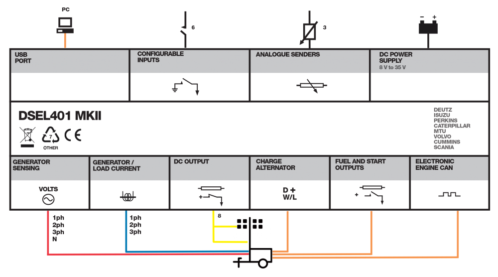
Connection Diagram

DSEL401 MKII connection diagram

Product Variants

 L401-01 - L401 MKII LTC (RTC)