Auto Mains (Utility) Failure Control Modules
DSE6120
Auto Mains (Utility) Control Module
The DSE 6120 is an Auto Mains (Utility) Failure Control Module developed to provide a wide range of operating and monitoring features for single diesel and gas gen-sets.
OVERALL SIZE
216 mm x 158 mm x 43 mm (8.5” x 6.2” x
1.5”)
PANEL CUTOUT SIZE
184 mm x 137 mm (7.2" x 5.3")
MAXIMUM PANEL THICKNESS
8.0 mm (0.3”)
This product is now obsolete
and has been replaced with:
DSE6120 MKIII –
Auto Mains (Utility) Failure Control Module
Request a Quote
Product Highlights
Key Features
Key Benefits
- Additional Features
- Engine hours counter.
- Engine pre-heat.
- Remote start input.
- Battery voltage monitoring.
Specification
DC SUPPLY
CONTINUOUS VOLTAGE RATING
8 V to 35 V Continuous
CRANKING DROPOUTS
Able to survive 0 V for 50 mS, providing supply was at least 10 V before dropout and supply recovers to 5 V. This is achieved without the need for internal batteries. LEDs and backlight will not be aintained
during cranking.
MAXIMUM OPERATING CURRENT
178 mA at 12 V, 95 mA at 24 V
MAXIMUM STANDBY CURRENT
88 mA at 12 V, 50 mA at 24 V
CHARGE FAIL/EXCITATION RANGE
0 V to 35 V
MAINS (UTILITY)
VOLTAGE RANGE
15 V - 333 V AC (L-N)
FREQUENCY RANGE
3.5 Hz to 75 Hz
OUTPUTS
OUTPUT A (FUEL)
2 A DC at supply voltage
OUTPUT B (START)
2 A DC at supply voltage
AUXILIARY OUTPUTS C,D,E & F
2 A DC at supply voltage
GENERATOR
VOLTAGE RANGE
15 V - 333 V AC (L-N)
FREQUENCY RANGE
3.5 Hz to 75 Hz
MAGNETIC PICK-UP
VOLTAGE RANGE
+/- 0.5 V to 70 V
FREQUENCY RANGE
10,000 Hz (max)
Environmental Testing Standards
ELECTRO-MAGNETIC COMPATIBILITY
BS EN 61000-6-2
EMC Generic Immunity Standard for the Industrial Environment.
BS EN 61000-6-4
EMC Generic Emission Standard for the Industrial Environment.
ELECTRICAL SAFETY
BS EN 60950
Safety of Information Technology Equipment, including Electrical Business Equipment.
TEMPERATURE
BS EN 60068-2-1
Ab/Ae Cold Test -30°C.
BS EN 60068-2-2
Bb/Be Dry Heat +70°C.
VIBRATION
BS EN 60068-2-6
Ten sweeps in each of three major axes.
5 Hz to 8 Hz @ +/-7.5 mm, 8 Hz to 500 Hz @ 2 gn.
HUMIDITY
BS EN 60068-2-30
Db Damp Heat Cyclic 20/55° C @ 95% RH 48 Hours.
BS EN 60068-2-78
Cab Damp Heat Static 40° C @ 93% RH 48 Hours.
SHOCK
BS EN 60068-2-27
Three shocks in each of three major axes 15 gn in 11 ms.
DEGREES OF PROTECTION PROVIDED BY ENCLOSURES
BS EN 60529
IP65 - Front of module when installed into the control panel with the optional sealing gasket.
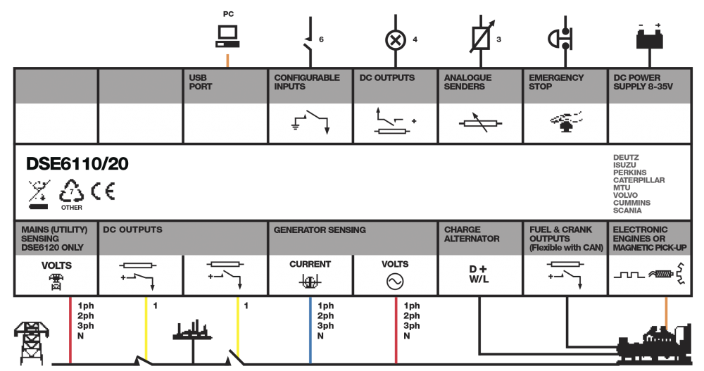
Connection Diagram
Product Variants
6120-01 - 6120 AMF CONTROLLER MPU FREQUENCY
6120-03 - PR - 6120 MKII AMF