Auto Mains (Utility) Failure Control Modules
DSE6020MKII
Auto Mains (Utility) Control Module
The DSE 6020 MKII is an Auto Mains (Utility) Failure Control Module developed to provide a wide range of operating and monitoring features for single diesel and gas gen-sets.
| To view UL Certification click here. |
216 mm x 158 mm x 43 mm (8.5” x 6.2” x 1.5”)
PANEL CUTOUT SIZE
184 mm x 137 mm (7.2" x 5.3")
MAXIMUM PANEL THICKNESS
8.0 mm (0.3”)
WEIGHT
0.48kg
PRODUCT VARIANTS
6020-03 - MKII Auto Mains (Utility) Failure Control Module
6020-04 - MKII Auto Mains (Utility) Failure Control Module (Htr)
Request a Quote
Product Highlights
Key Features
Key Benefits
- Additional Features
- Engine maintenance alarms (3).
- Engine speed protection.
- Engine hours counter.
- Engine pre-heat.
- Engine run time scheduler.
- Engine idle control for start/stop.
- Manual fuel pump control.
- Backed-up real time clock.
- Battery voltage monitoring.
- Start on low battery.
- Configurable remote start input.
- Alternative configuration (1).
Specification
DC SUPPLY
CONTINUOUS VOLTAGE RATING
8 V to 35 V Continuous
CRANKING DROPOUTS
Able to survive 0 V for 50 mS, providing supply was at least 10 V before dropout and supply recovers to 5 V. This is achieved without the need for internal batteries. LEDs and backlight will not be maintained
during cranking.
MAXIMUM OPERATING CURRENT
100 mA at 12 V, 105 mA at 24 V
MAXIMUM STANDBY CURRENT
60 mA at 12 V, 55 mA at 24 V
MAXIMUM SLEEP CURRENT
40 mA at 12 V, 35 mA at 24 V
GENERATOR & MAINS (UTILITY)
VOLTAGE RANGE
15 V to 415 V AC (Ph to N)
26 V to 719 V AC (Ph to Ph)
FREQUENCY RANGE
3.5 Hz to 75 Hz
INPUTS
DIGITAL INPUTS A to F
Negative switching
ANALOGUE INPUTS A to C
Configurable as:
Negative switching digital input
0 Ω to 480 Ω
ANALOGUE INPUT D
Configurable as:
Negative switching digital input
0 V to 10 V
4 mA to 20 mA
0 Ω to 480 Ω
OUTPUTS
OUTPUT A (FUEL)10 A short term, 5 A continuous,
at supply voltage
OUTPUT B (START)
10 A short term, 5 A continuous,
at supply voltage
AUXILIARY OUTPUTS C, D, E & F
2 A DC at supply voltage
Environmental Testing Standards
ELECTRO-MAGNETIC COMPATIBILITY
BS EN 61000-6-2
EMC Generic Immunity Standard for the Industrial Environment.
BS EN 61000-6-4
EMC Generic Emission Standard for the Industrial Environment.
ELECTRICAL SAFETY
BS EN 60950
Safety of Information Technology Equipment, including Electrical Business Equipment.
TEMPERATURE
BS EN 60068-2-1
Ab/Ae Cold Test -30°C.
BS EN 60068-2-2
Bb/Be Dry Heat +70°C.
VIBRATION
BS EN 60068-2-6
Ten sweeps in each of three major axes.
5 Hz to 8 Hz @ +/-7.5 mm, 8 Hz to 500 Hz @ 2 gn.
HUMIDITY
BS EN 60068-2-30
Db Damp Heat Cyclic 20/55° C @ 95% RH 48 Hours.
BS EN 60068-2-78
Cab Damp Heat Static 40° C @ 93% RH 48 Hours.
SHOCK
BS EN 60068-2-27
Three shocks in each of three major axes 15 gn in 11 ms.
DEGREES OF PROTECTION PROVIDED BY ENCLOSURES
BS EN 60529
IP65 - Front of module when installed into the control panel with the optional sealing gasket.
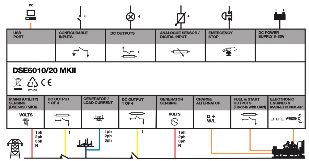
Connection Diagram
Product Variants
6020-03 - MKII Auto Mains (Utility) Failure Control Module
6020-04 - MKII Auto Mains (Utility) Failure Control Module (Htr)