Auto Mains (Utility) Failure Control Modules

DSE4520 MKII

Auto Mains (Utility) Failure Control Module
The DSE4520 MKII is a compact Auto Mains (Utility) Failure Control Module that has been developed to provide an outstanding range of features within a compact enclosure. 

THE MODULE CAN BE CONFIGURED FOR USE AS AN AUTO START CONTROL MODULE. 

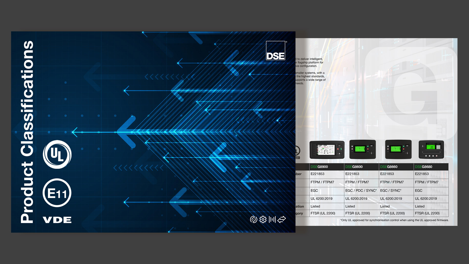
To view UL Certification click here.
OVERALL SIZE
140 mm x 113 mm x 43 mm (5.5” x 4.4” x 1.5”) 
PANEL CUTOUT SIZE
118 mm x 92 mm (4.6" x 3.6")
MAXIMUM PANEL THICKNESS
8.0 mm (0.3”)
WEIGHT
0.26kg
PRODUCT VARIANTS
4520-05 - 4520 Auto Mains (Utility) Failure Control Module (Ct, Rtc)

Request a Quote

e -
Please select a product
Please enter a quantity
e +

add another product

Please enter your title
Please enter your first name
Please enter your surname
Please enter your company name
Please select your country
Please enter a delivery Country/State
Please enter your email
Please enter your mobile number
Webform URL: Website Option: Webform: Named Distributor: Distributor's Email: Named Reseller: Reseller's Email:


l

Product Highlights

Key Features & Benefits

Key Features

Key Benefits

Configurable for use as an AMF or Auto Start Control Module.
Delivers outstanding flexibility. Customers only need to stock one part for multiple applications.
CAN & alternator speed sensing.
Provides full monitoring flexibility.
Largest back-lit display in its class
Provides clear and easy to read information pages.
Heated display option.
Ensures the display continues to operate in extreme cold weather conditions.
Backed-up real time clock.
Ensures data is not lost when module is disconnected from its power source.
Fully configurable via DSE Configuration Suite PC Software
Provides complete user-friendly configuration and easy-to-use high-level system control & monitoring.
Power save mode.
Minimises battery drain when the system is not in use.
3-phase generator and mains (utility) sensing.
Provides true generator and mains (utility) sensing.
600 V ph-ph nominal system compatibility.
Provides global flexibility.
Generator & load power monitoring (kW, kV A, kV Ar, pf).
Provides clear accurate power measurement information.
Accumulated power monitoring (kW h, kVA h, kVAr h).
Provides a true indication of the amount of energy the generator has provided.
Generator overload protection (kW).
Provides engine overload protection.
Generator/load current monitoring & protection.
Protects generator against overload.
Fuel and start outputs (configurable on CAN).
Provides multiple installation options.
5 V output.
A single digital output is available to power senders.
Text mode.
Users can configure the module to show text instead of the standard icon based display.
Compatible with a wide range of senders.
Accommodates a wide range of senders and temperatures.
Configurable fuel and crank outputs.
Provides increased flexibility for multiple applications.
Improved engine maintenance through coolant temperature.
Enhancements have been made to the engine coolant temperature to include a pre alarm for advanced warning.
Load unbalanced alarm.
Provides protection against unbalanced loads damaging the alternator.
  • Additional Features
  • Fuel solenoid pulling circuit
  • On-screen line diagram on/off functionality
  • Configurable CAN instrumentation (10)
  • Water in fuel digital input
  •  
  • Tank bund alarm digital input
  • Generator at rest output
  • ECU periodic wake-up for information retrieval
  •  
  • Back-light power-save mode
  • Adjustable delay crank timer
  • Pre/post heat functionality
  •  
  • Overload protection
  • Mains/generator A/C system selection
  • Output timer for external audible alarm
  •  

Specification

DC SUPPLY

CONTINUOUS VOLTAGE RATING
8 V to 35 V Continuous

CRANKING DROPOUTS
Able to survive 0 V for 50 mS, providing supply was at least 10 V before dropout and supply recovers to 5 V. This is achieved without the need for internal batteries. LEDs and backlight will not be maintained during cranking.

MAXIMUM OPERATING CURRENT
85 mA at 12 V, 96 mA at 24 V

MAXIMUM STANDBY CURRENT
51 mA at 12 V, 47 mA at 24 V

MAXIMUM SLEEP CURRENT
35 mA at 12 V, 32 mA at 24 V

MAXIMUM DEEP SLEEP CURRENT
<10 uA at 12 V, <10 uA at 24 V

OUTPUTS

OUTPUT A (FUEL)
10 A short term, 5 A continuous,
at supply voltage

OUTPUT B (START)
10 A short term, 5 A continuous,
at supply voltage

AUXILIARY OUTPUTs C & D
2 A DC at supply voltage ­­


GENERATOR

VOLTAGE RANGE
15 V to 415 V AC (Ph to N)
26 V to 719 V AC (Ph to Ph)

FREQUENCY RANGE
3.5 Hz to 75 Hz

Environmental Testing Standards

ELECTRO-MAGNETIC  COMPATIBILITY
BS EN 61000-6-2
EMC Generic Immunity Standard for the Industrial Environment.
BS EN 61000-6-4
EMC Generic Emission Standard for the Industrial Environment.

ELECTRICAL SAFETY
BS EN 60950
Safety of Information Technology Equipment, including Electrical Business Equipment.

TEMPERATURE
BS EN 60068-2-1
Ab/Ae Cold Test -30°C.
BS EN 60068-2-2
Bb/Be Dry Heat +70°C.

VIBRATION
BS EN 60068-2-6
Ten sweeps in each of three major axes.
5 Hz to 8 Hz @ +/-7.5 mm, 8 Hz to 500 Hz @ 2 gn.

HUMIDITY
BS EN 60068-2-30
Db Damp Heat Cyclic 20/55° C @ 95% RH 48 Hours.
BS EN 60068-2-78
Cab Damp Heat Static 40° C @ 93% RH 48 Hours.

SHOCK
BS EN 60068-2-27
Three shocks in each of three major axes 15 gn in 11 ms.

DEGREES OF PROTECTION PROVIDED BY ENCLOSURES
BS EN 60529
IP65 - Front of module when installed into the control panel with the optional sealing gasket.
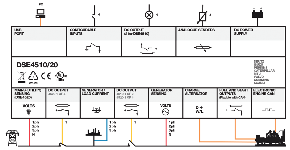
Connection Diagram

DSE4520 MKII connection diagram

Product Variants

4520-05 - 4520 Auto Mains (Utility) Failure Control Module (Ct, Rtc)